Wednesday, May 11, 2011

Spying On Your Waste

Spying On Your Waste
I was very interested to hear about the recent scheme of waste tracking which is being implemented by MIT, 3000 pieces of rubbish in London, Seattle and New York will be fitted with hi-tech tags which use mobile phone technology to send out a real time tracking signal. In effect this means that MIT will be able to watch exactly where the waste is moving to in real time.
The aim is to highlight exactly what happens to the waste we throw away and that it doesn't always end up where we think, sometimes it will even end up in a completely different country, where the approach to waste management is not as stringent and as such it can end up becoming a pollutant.
The BBC have written a quite extensive article about the technology behind the transmitters and what MIT are hoping to achieve in the lifetime of the project.
I think that projects like these are great tools to raise awareness of our throw-away lifestyle and that waste doesn't simply disappear when the bin man collects it.

One Motor Walker Robot Without uC

One Motor Walker Robot Without uC
Robot is interesting electronic project. We often see that robot project need a microcontroller as main processor. But if you don't have any programming skill yet, don't worry, you can build one motor walker robot by Jerome Demers. Yes the it's a walker robot without a microcontroller. The robot is base on the principal of B.E.A.M robotics! Building simple and elegant robot inspired by insect.

PIC LCD Oscilloscope for Spectrum Analyzers

PIC LCD Oscilloscope for Spectrum Analyzers
This is simple and inexpensive LCD oscilloscope for spectrum analyzer display. The project use PIC 16F876A as main processor. Although a small LCD screen is not as good as analog oscilloscope, a LCD oscilloscope may be very useful in field measurements, for battery operation or you need different measurement at the same time along with oscilloscope.
The 80dB scale of this LCD oscilloscope can be adjusted with the two trimmers providing the reference voltages to the A/D converter. The operation of the LCD oscilloscope is slightly different between the 80dB mode and the 40dB mode. In the 80dB mode, the trace is always visible and saturates on the bottom or top of screen. In the 40dB mode, the trace runs out of the screen and only the central part of the original 80dB scale is displayed. This project designed by Matjaz Vidmar.

Download Source code, documentation and schematic

Thursday, March 31, 2011

AVR Electronic Combination Lock


AVR Electronic Combination Lock
Code Lock AVR is electronic combination lock based on AVR microcontroller AT90S2313 or ATtiny2313. User code is consisted of 1 to 8 digits. If the code is entered in the correct sequence, then after 1 second the relay and the electric striker (in the door) switch on for 1 second and then switch off again. User code can be changed via 3x4 matrix keypad. Program in hex code is 2 kB long.
tag : electronic lock, combination keylock, Avr project src

AVR Project Wii Conductor


AVR Project Wii Conductor
This AVR project is a simplified implementation of Wii-Music, utilizing a Nintendo Wii Remote (“Wiimote”) to play a gesture-based music game with the player as a virtual music conductor. The project exploited two of the Wiimote’s features: its wand-like shape and the embedded 3-D accelerometers. By interfacing between Microcontroller AVR ATmega 644 and Wiimote, the project able wirelessly transmit motion gestures and button pushes to the MCU. The MCU uses these inputs to create sound by means of Direct Digital Synthesis (DDS).
Tags: Wii Conductor, Simplified Wii Music, Microcontroller AVR project src

Arduino Digital Thermometer


Arduino Digital Thermometer
This Digital Thermometer based on famous Arduino board and LM35DZ as temperature sensor. The sensor component has three pins, +5V, ground and a variable voltage output to indicate the temperature. This simple project wired the sensor output straight to the Arduino's analogue input 0. As display, it use two line LCD (a Displaytech 162B).
Tags : Temperature Measurement, Digital Thermometer, Arduino project src

I2C Bus Analyzer with USB link to PC

I2C Bus Analyzer with USB link to PC
I2C-bus analyzer is a electronic project that has function to capture all transmissions via I2C/TWI bus, decode it and send to PC via virtual RS-232 port. Received data can be displayed by any terminal program on PC computer. The project use ATTiny2313 microcontroller with 20MHz crystal as main part. Link to PC are realized by FTDI FT245RL on UM245R module.more

Download : Schematic, PCB bottom layer, PCB top layer (wire jumpers), PCB top overlay, Firmware

Saturday, March 26, 2011

Switch-Mode Battery Charger Circuit

Fast, High Effi ciency, Standalone NiMH/NiCd Battery Charging Circuit
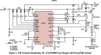
Figure 1 shows a fast, 2A charger featuring the high effi ciency LTC4011 550kHz synchronous buck converter. The LTC4011 simplifies charger design by integrating all of the features needed to charge Ni-based batteries, including constant current control circuitry, charge termination, automatic trickle and top off charge, automatic recharge, programmable timer, PowerPath control and multiple status outputs. Such a high level of integration lowers the component count, enabling a complete charger to occupy less than 4cm2 of board area. more

Battery Charger Delivers 2.5A With >96% Efficiency
Battery chargers are usually designed without regard for efficiency, but the heat generated by low-efficiency chargers can present a problem. For those applications, the charger of Figure 1 delivers 2.5A with efficiency as high as 96%. It can charge a battery of one to six cells while operating from a car battery.
Figure 1. Modified feedback paths transform this switch-mode power-supply circuit for notebook computers into a high-efficiency battery charger. more pdf

AVR Based Diode Temperature Meter


AVR Based Diode Temperature Meter
This is Multi channel diode temperature meter project with Microcontroller AVR AT90S2333 as main controller. It can be use to replace thermister temperature meter.
Front end of the temperature sensor and amplifier circuit consists of constant current. Approximately a constant current of 63µA sensor (diode) in the sink, a diode voltage drop of 3-fold amplification and A / D converter (10bit, 3.3V/fs) type. Drift in this block is the main cause of measurement error, the components must be selected as the low temperature drift.
Where an adjustment is not analog, EEPROM calibration parameters are calculated from the temperature to make sure that you store in it. The calibration process is required for proper equipment such as computer terminals instead of the driver. Some cases, ISP via cable (N81, 38.4kbps) has been to enter the calibration mode is turned on and connected.
Download : Schematic and source code

AVR Nikon Camera Remote Control


AVR Nikon Camera Remote Control
This is an IR remote control for Nikon cameras. The circuit project is very simple: an ATtiny13V, button, transistor, resistor, IR diode and 3V battery. You can also connect the IR diode directly to the ATtiny13V, but that will limit the LED current and therefore the range. The project is compatible with the Nikon ML-L3 remote control. Supported cameras include: D40, D40X, D50, D60, D70, D70s, D80, and Coolpix 8400 8800. This project created by Dick Streefland
Download: Schematic and source code

charger with charge timer and LED-status outputs


MAX846A Li+ charger with charge timer and LED-status outputs, controlled by an 8-pin Microcontroller
In this example, a small external µP enhances the MAX846A, forming a complete desktop-charger system that includes user-interface functions such as the LEDs in Figure (to indicate the charge process and status). The MAX846A is designed for this type of operation. Its auxiliary linear regulator and µP-reset circuit (to support the external µC) reduces the cost of a typical desktop-charger application.

Microcontroller Battery Charger Circuit


Microcontroller Battery Charger Circuit
In applications where a microcontroller is available, the MAX1640/MAX1641 can be used as a low-cost battery charger (Figure 5). The controller takes over fast charge, pulse-trickle charge, charge termination, and other smart functions. By monitoring the output voltage at VOUT, the controller initiates fast charge (set D0 and D1 high), terminates fast charge and initiates top-off (set D0 high and D1 low), enters trickle charge (set D0 low and D1 high), or shuts off and terminates current flow (set D0 and D1 low).
Download : MAX1640 Daasheet

Magnetic Rotary Encoder to Microcontroller AS5145 circuit


Magnetic Rotary Encoder to Microcontroller AS5145 circuit
12-Bit Programmable Magnetic Rotary Encoder
The AS5145 is a contact less magnetic rotary encoder foraccurate angular measurement over a full turn of 360 degrees. It is a system-on-chip, combining integrated Hall elements,analog front end and digital signal processing in a single device. To measure the angle, only a simple two-pole magnet, rotating over the center of the chip, is required. The magnet may beplaced above or below the IC.The absolute angle measurement provides instant indication of the magnet’s angular position witha resolution of 0.0879º = 4096 positions per revolution. This digital data is available as a serial bit stream and as a PWMsignal.An internal voltage regulator allows the AS5145 to operate at either 3.3V or 5V supplies.Typical magnet (6x3mm) and magnetic field distribution

Daisy Chain Mode
The Daisy Chain mode allows connection of severalAS5145’s in series, while still keeping just one digital input for data transfer (see “Data IN” in Figure 9). This mode is accomplished by connecting the data output (DO; pin 9) to the data input (PDIO; pin 8) of the subsequent device. The serial data of all connected devices is read from the DO pin of the first device in the chain. The length of the serial bit stream increases with every connected device, it is n * (18+1) bits: n= number of devices. e.g. 38 bit for two devices, 57 bit for three devices, etcetc.
Download : AS5145 Datasheet

AVR flash trigger

AVR flash trigger
The SPOT (strobist-project-opensource-trigger)is a remote flash trigger radio transceiver. It lets you adjust and trigger off-camera flashes remotely. It has two modes of operation: First, As a transmitter it sits on the hot shoe of a camera and forwards electrical flash trigger signals from the camera to slave flashes via radio. Secondly, As a receiver it is connected to a small hot shoe ("system") flash. The project use microcontroller AVR ATmega 8L as main controller.
Download : Documentation and source

Thursday, March 24, 2011

Implementation USB to microcontroller (AVR)

Implementation USB to microcontroller (AVR)
Purpose of this article is to inform readers about implementation USB interface into singlechip microcontroller, which this interface directly not supports. Simply: implementation USB interface on firmware level (similar as emulation of RS232 Serial interface in microcontrollers, which not have RS232 Serial support). This project includes development of firmware on microcontroller side, driver development on computer side (for Windows operating system), development of DLL library for functions calling from another programs (programmers level) and development of demo program (users level), which shows all functions of this device. Device is named IgorPlug-USB (AVR) (as successor of my previous device for computer remote control IgorPlug - serial port version).

MCU Serial Interface

USB to MCU Serial Interface
An example of using the FT232R as a USB to Microcontroller (MCU) UART interface is shown in Figure 7.4. In this application the FT232R uses TXD and RXD for transmission and reception of data, and RTS# / CTS# signals for hardware handshaking. Also in this example CBUS0 has been configured as a 12MHz output to clock the MCU. Optionally, RI# could be connected to another I/O pin on the MCU and used to wake up the USB host controller from suspend mode. If the MCU is handling power management functions, then a CBUS pin can be configured as PWREN# and would also be connected to an I/O pin of the MCU.
FT245BM datasheet pdf

Plane Autopilot


Plane Autopilot
ArduPilot is a full-featured autopilot based on the Arduino open-source hardware platform. It is a custom PCB with an embedded processor (ATMega168) combined with circuitry to switch between RC control and autopilot control (that's the multiplexer/failsafe, otherwise known as a "MUX"). This controls navigation (following GPS waypoints) and altitude by controlling the rudder and throttle. These components are all open source. This autopilot is fully programmable and can have any number of GPS waypoints (including altitude) and It uses infrared (thermopile) sensors for stabilization and GPS for navigation.
Download Project : Plane Autopilot

Debug Design

Debugging Tool
In-Circuit-Debugger is handy and easy PIC debugging tool for PIC programmers that interface to the target PIC placed- board. The device comes with MPLAB plug-ins that provides a full rich set of commands and functions in order to debug your code in real time. The project created by Electrical Engineer Atanasios Melimopoulos.
After hours of using some brands of ICDs, ICD2, etc. on different projects, I faced some hardware situations where the two pin interface ICD <-> PIC becomes annoying and sometimes difficult to work around. Apart from the fact that your target PIC must run at selected clock frequencies that allows the ICD-Uart baudrate multiplier to fit. Also, some pics do not allow the same on-hook commands upon which ICDs are based. There is no electrical isolation between the pic-target board and the USB–Serial PC-GND interface.
Download Project : Circuit debugger

Digital Clock LED 7 Segment Displays

Digital Clock using Classic LED 7 Segment Displays
This is a simple digital clock project using PIC16F887 and classic LED 7-Segment from HP 5082-7414 created by punky. The displays are bright red and sun light viewable. Each clock consumes about 0.25W (50mA, 5V) when the PIC16F887 operates at 250kHz (display refresh rate is about 61Hz).
download project : Download

Saturday, October 16, 2010

Infrared Switch circuit

Infrared Switch circuit diagram
Infrared Switch circuit
Infrared Switch circuit for common use, please visit this page for complete explanation.
This is a single channel (on / off) universal switch that may be used with any Infra Red remote control using 36-38kHz. (This is a very common remote handset frequency). In place of IR1 a TSOP1738 receiver may be used.
Any "button" of any remote control may be used to work this universal switch. The button must be pressed for about one and a half seconds (determined by R3 and C2) before the relay will operate. The circuit will remain in this state (latched) until reset. To reset, any button is pressed on the remote handset and held for a short duration.
For example, if you were watching TV, you could press and hold any button on the TV remote to trigger the circuit. In order not to change channel, you could press the button of the channel you are watching. You can connect anything to the relay, for example a lamp, but make sure that the relay contacts can handle the rated voltage and current.